Hobbild celebrates 25 years!
What is CNC
CNC is short for “Computer Numeric Control ”, that is a machine for mechanical processing, see lathe or milling machine, which he comes controlled by a computer to perform machining or pieces.
A car CNC hobbyist type is generally made up from the following parts:
Computer
CNC control program
The file in Gcode of the workpiece or processing from to execute
The electronic control of the CNC (Stepperdrivers)
The electronic control power supply unit.
The step motors step (stepmotor)
CAD, CAM and various interpreters programs.
The machine that performs the work
Computer
On this computer it is normally installed the CNC control program
An old Pentium with about 3Ghz of frequency e 1 Gig of ram could be generally sufficient for programs such as Mach3 or LinuxCNC.
The parallel port is the most commonly used communication method between computers and electronic control, but USB port systems are becoming more and more accessible and performing.

CNC control program
It is the fundamental program with which the cutter is controlled.
Its job is to turn the file into Gcode (normally generated with a CAM program), in a series of signals (step and direction), to be sent to the step motors step of the cutter.With this program it is also possible to perform manual movements of the milling axes, or by introducing appropriate commands on the video window of the control program.
It is also possible to directly enter and execute commands in Gcode.
Generally on a program window it is possible to see the drawing of the inherent tool path the workpiece.
A further window displays the coordinates of the three axes and in other windows other information about settings and work in progress are displayed.Each control program has a section dedicated to the parameters of settings which are generally:
Identification of the parallel port that communicates with the computer.
The setting of the pins of this gate, with which the association of the step / direction is determined from each stepper motor with its pin and the various input and output signals used.
The setting of the displacement value for each rotation step of the motors.
The maximum speeds and accelerations that the engines can hold.
Any game compensations (backlash correction) that may be present between the bushings and threaded rods of the displacement axes.
Settings for any installed limit switches.
SOFTWARE
File of the part or machining to be performed (G-Code of the machining)
It is a file generally created by a CAD / CAM program, or it can be generated by an ACE type conversion program which derives it from the drawing file in .dxf format previously made with a program CAD.
This file is in ASCII format and can be edited with Notepad, recommended only when you become more experienced.
Normally this file is written in language G-code, sometimes in HPGL (file used for the plotting of drawings).
A file Gcode it is made up of: Blocks, Commands and Coordinates.
Blocks: they are ASCII lines containing commands and coordinates, they are practically one or more commands that must be executed before moving on to the next block.
Commands: they consist of a letter and a number, the most common are the following: there are many other M-type commands used for auxiliary controls during the processing phase.
G00 Rapid feed with linear interpolation
G01 Linear interpolation (feed with working motion)
G02 Circular interpolation clockwise
G03 Circular interpolation counterclockwise
G04 Timed stop
G17 Choice of the XY plane
G18 Choice of the XZ plane
G19 Choice of the YZ plane
G70 Measurements in inches
G71 Measurements in mm
o G90 Absolute coordinates
G91 Relative coordinates.
Although the file in Gcode format is built with standard and unified commands, it cannot be read by any CNC control program.
At the hobby level, the CNC control programs that run under DOS are able to recognize and process only a small part of these Gcode commands and are generally sufficient for even complex machining operations.
This set of commands that our CNC control program can recognize is called "Post-processor".
The CAM program, therefore, which will have to transform the drawing of the part to be made into the Gcode file, will have to be set and set up in such a way as to use the Post-processor of the CNC control program that will control the cutter, i.e. it will have to use only a certain type of Gcode commands that can be interpreted by the CNC control program.
GCODE
Electronic control (stepperdriver or driver)
It consists of one or more electronic boards that power and make the stepper motors move step in the right sequence and in a synchronized manner.
Electronic control can generally be of two types:
For single pole motors, it can be recognized by visible resistances in the vicinity of the motor connection connector.
They are not very expensive checks.
Motors usually have 5 or 6 wires and don't have much power.For bipolar motors which normally have 4,6 or 8 wires, never 5.
They are more performing and the electronic components that make up the control are sophisticated for their operation.
For bipolar motors, the power supply voltage normally ranges from 5 to 20 times the rating indicated on the motor.Usually the power supply part also resides inside the box of this control.
To connect the electronic control to the computer, the DB25 connector (that of the parallel port) is normally used, but also via USB or RS 232.

Power Supply
The power supply for the motors and for the power supply of the boards is taken from this group.
The power supply, in the case of drivers for bipolar motors, is supplied by a transformer with a secondary of 12/40 Volts and a current of about 3/10 Ampers.
usually this voltage is rectified by a diode bridge and smoothed by an electrolytic capacitor of about 10,000mF.To power the boards, a second transformer is normally used which supplies a voltage which is then adjusted to 5 Volts.
Usually this group is placed inside the Electronic Control for hobby solutions.

Stepper motors (step motor)
For our use we usually use motors of "surplus" origin, that is, disassembled from discarded machines (see printers), or from warehouse remains no longer used.
The prices are therefore more affordable than buying new engines.For bipolar use, motors with 4, 6 or 8 wires are used.
For single-pole use with 5, 6 or 8 wires.
The motors are also classified by the number of steps they take to make a revolution, on CNC milling machines usually 200 step (1.8 degrees) motors are used.
48 step motors are inexpensive but not very suitable for use on CNC milling machines.
The engines obtained from today's inkjet printers are very small and of little power .... I do not recommend them.

CAD, CAM programs and various interpreters
With the CAD we design the part which is then machined.
The best known is Autocad, but many other CADs, even better ones, can be used, the file extension is usually .dxfWith the CAM we transform the design file from .dxf to a G-code file.
It will be this G-code file that will be read by the CNC control program that will allow our cutter to perform the machining.
If we do not have a CAM program, we can use simple conversion programs or interpreters that transform the .dxf file into G-code, if you search the web you will find several.There are CNC mill control programs that already have a CAM inside them, see DeskCNC, or can convert a file from .dxf to G-code, see Kcam4.
An excellent and very simple CAM program is ArtCam Insignia, in the Express version it has an affordable price.
CAD
CAM
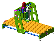
The machine that performs the work
-
It is the mechanical part of the whole system, on this we find the stepper motors and the milling tool that will perform the machining.
Its structure depends on the size of the pieces to be machined and the type of material we are going to process.
Hard materials will require a strong and rigid cutter structure.
There are usually three machining axes: X, Y and Z.
The guiding system of the three axes is very important that it is precise and smooth.
.png)